3 Way Diverting Valve Piping Diagram

Operation - Hot water only. Power starts at terminal 3 (HW On) in the programmer. This passes via the wiring centre terminal 6 to the cylinder thermostat. If heat is required, power continues to terminal 8 in the wiring centre, and on to the boiler and pump. The valve is not powered at all, and the spring holds it in position B, so water from.
3WAY VALVE
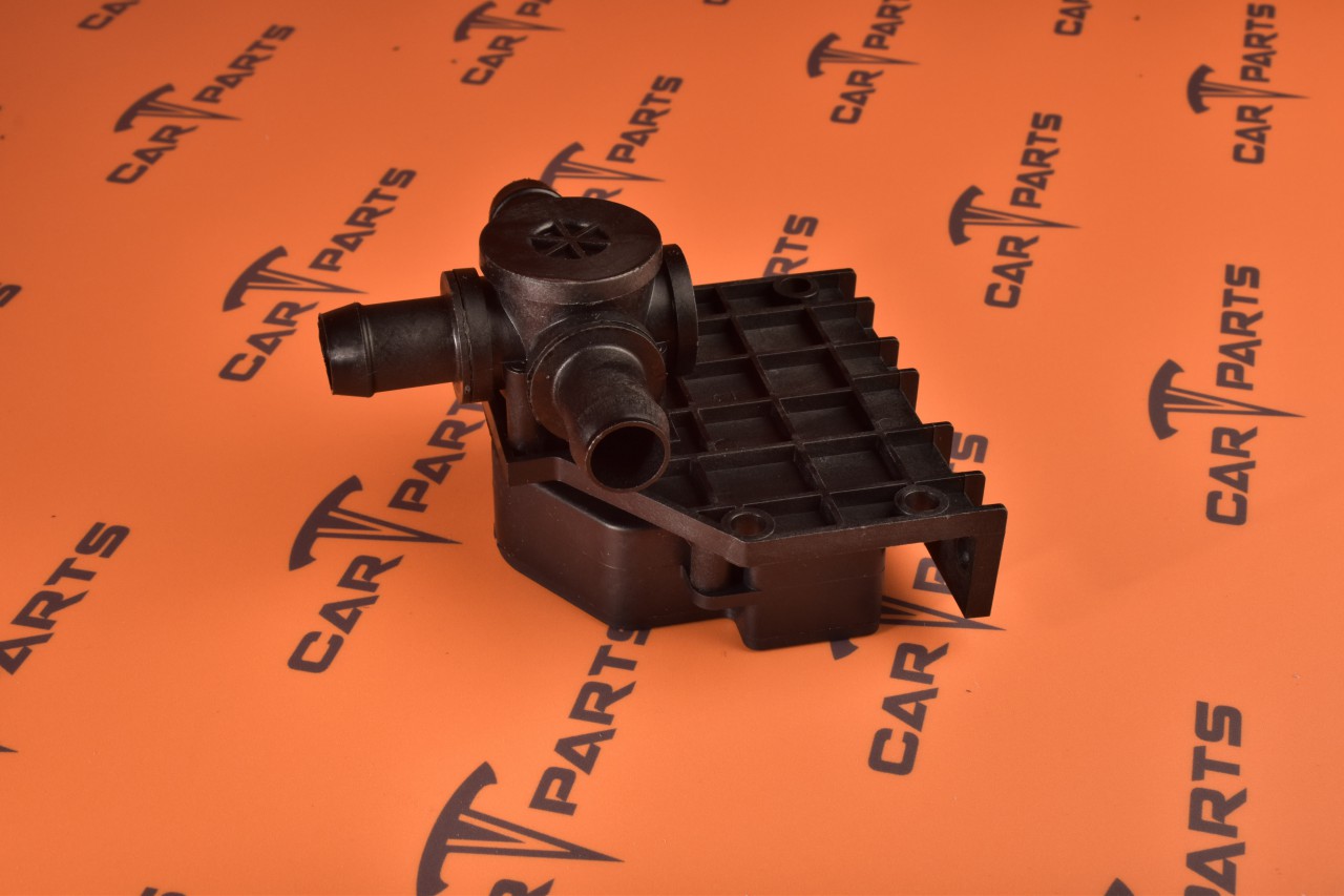
Step 2: Move actuator away from the valve body approximately 3⁄4" to disengage locking posts and stem. Step 1: Push in and hold release clip at the front of the actuator. CAUTION: Installation should only be per-formed by a qualified professional. Use of a solder with a melting point below 600°F is rec-ommended.
100K maint 5
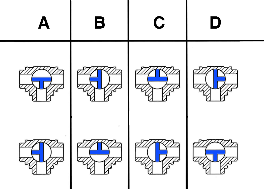
The valve symbols used in a P&ID diagram are standardized and the same globally. This makes it incredibly easy to read a diagram once the user knows what each symbol means. 2-way valves . Two-way valves can be recognized by the two triangles that point towards each other, such as the gate valve symbol seen in figure 2.
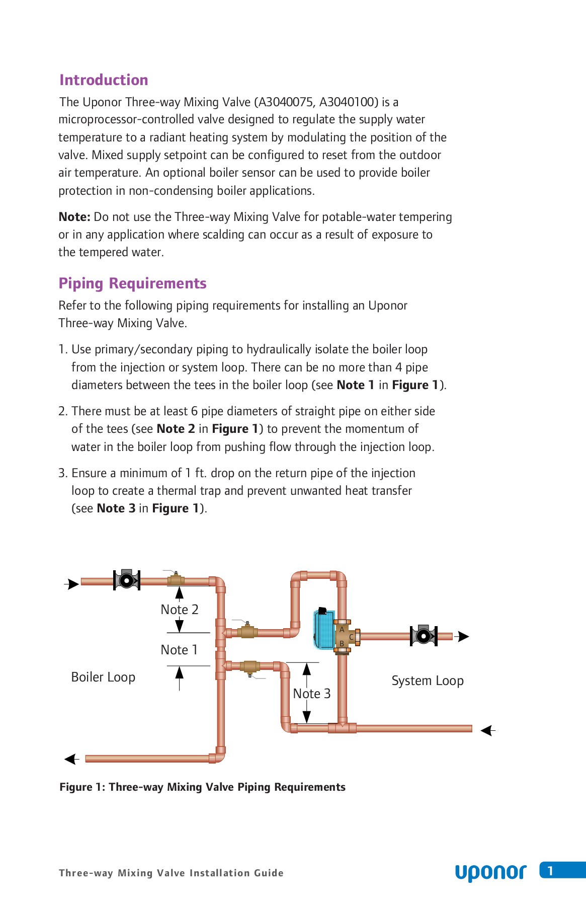
[DIAGRAM] 3 Way Mixing Valve Piping Diagram
Hey, It's U.S. Solid, in this video we will show you how to wire a 3 Wire CR02 Motorized ball valve.Once energized, connect red wire to posiive(+) and yellow.
[DIAGRAM] 3 Way Zone Valve Piping Diagram

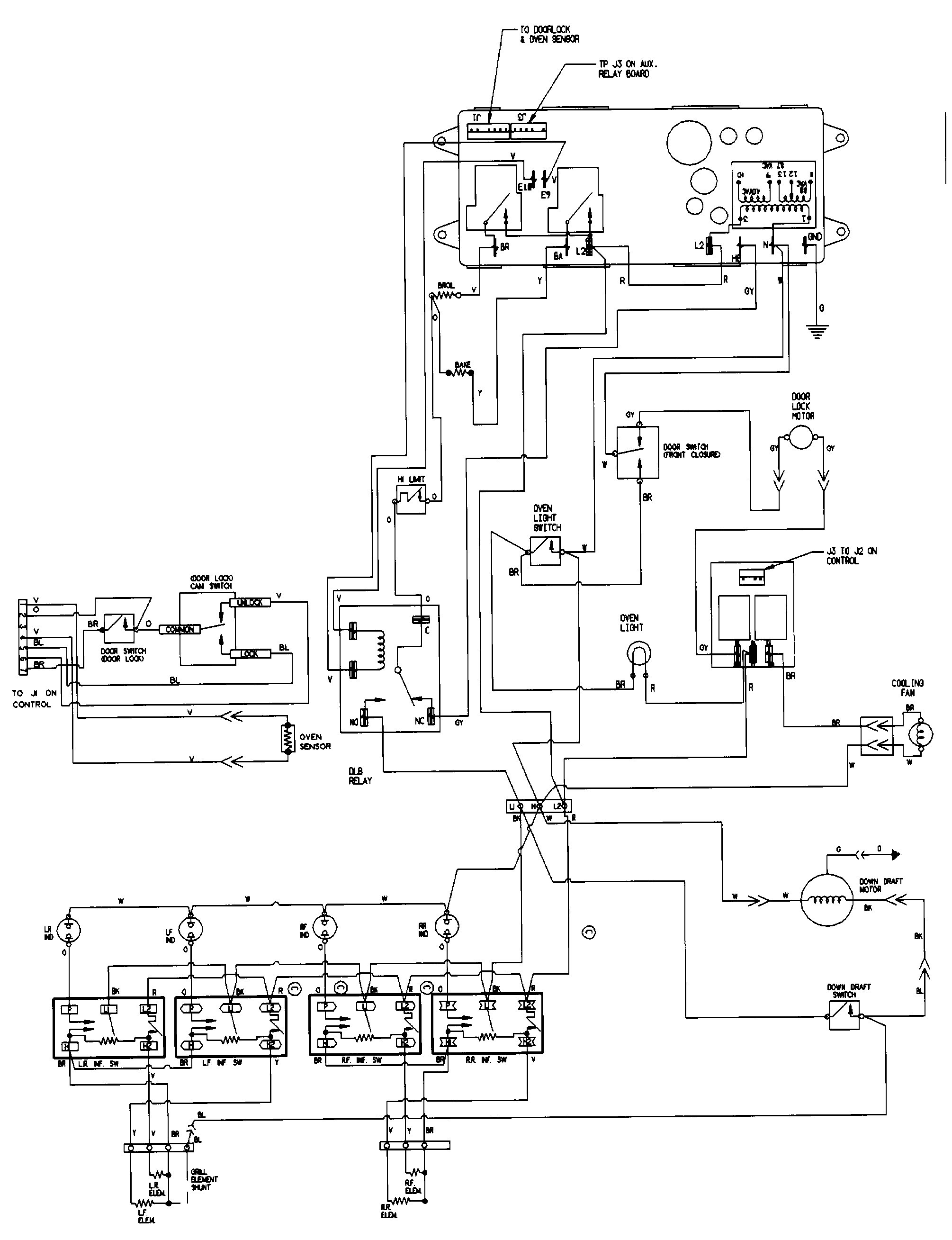
The wiring diagram is a crucial tool for installing and troubleshooting the Honeywell 3 Port system. It illustrates the electrical connections between the various components, such as the boiler, the valve, and the thermostat. The diagram typically includes color-coded wires and clearly labels the different terminals on the components.
[DIAGRAM] 3 Way Butterfly Valve Diagram

The 3-way valve schematic symbol typically consists of: A circle representing the valve itself. Three arrows or lines indicating the different flow paths. Labels or annotations specifying the function of each flow path, such as "inlet," "outlet," and "diverter". By referring to the schematic symbol, engineers can quickly identify.
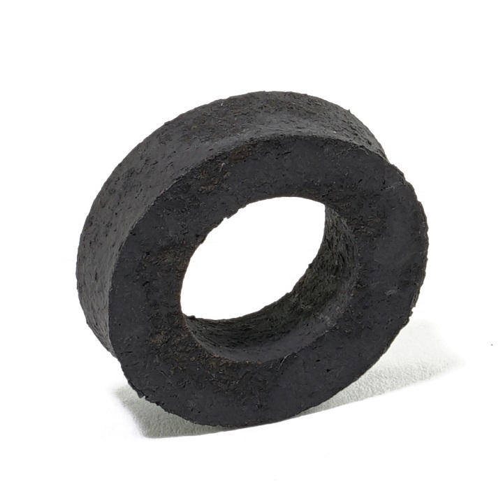
Packing, 3Way Valve The Brillman Company
See wiring diagram. Wire type and wire installation tips For most installations, 18 or 16 Ga. cable works well with Belimo actuators. Use code-approved wire nuts, terminal strips or solderless connectors where wires are joined. It is good practice to run control wires. L Series, 3-way, Ball Valve . 3-way . 2 2 2 3.
[DIAGRAM] Powers 3 Way Valve Diagram

Figure 6: Three-way Mixing Valve Typical Wiring Diagram. 6 www uponorpro com Sensor Wiring Do not apply power to the sensor terminals as this will damage the Three-way Mixing Valve. The wiring terminals for the sensors may be removed for ease of installation. Outdoor Sensor 1. Remove the screw and pull
Ep3 Wiring Diagram Wiring Diagram Pictures
VN SERIES ZONE VALVES INSTALLATION INSTRUCTIONS 3 31-00601-03 3. Eliminate air from the system. 4. Two-way valves are marked to show the flow direction, and the flow arrow must point in the flow direction of the medium for proper operation. NOTE: Port B is common port on three-way valves. For three-way valve mounting, see Fig. 3 and 4. 5. Stem.
3Way Ozone Valve Luer Connector and Luer Lock Fittings Simply O3 Simplyo3

3-way solenoid valves operate in a manner analogous to single-pole double-throw (SPDT) electrical switches: with two paths for flow sharing one common terminal. 3-way solenoid valves have three ports for fluid, and like 2-way valves may be referred to either as normally-open and normally-closed. Ports on a pneumatic 3-way valve are commonly.
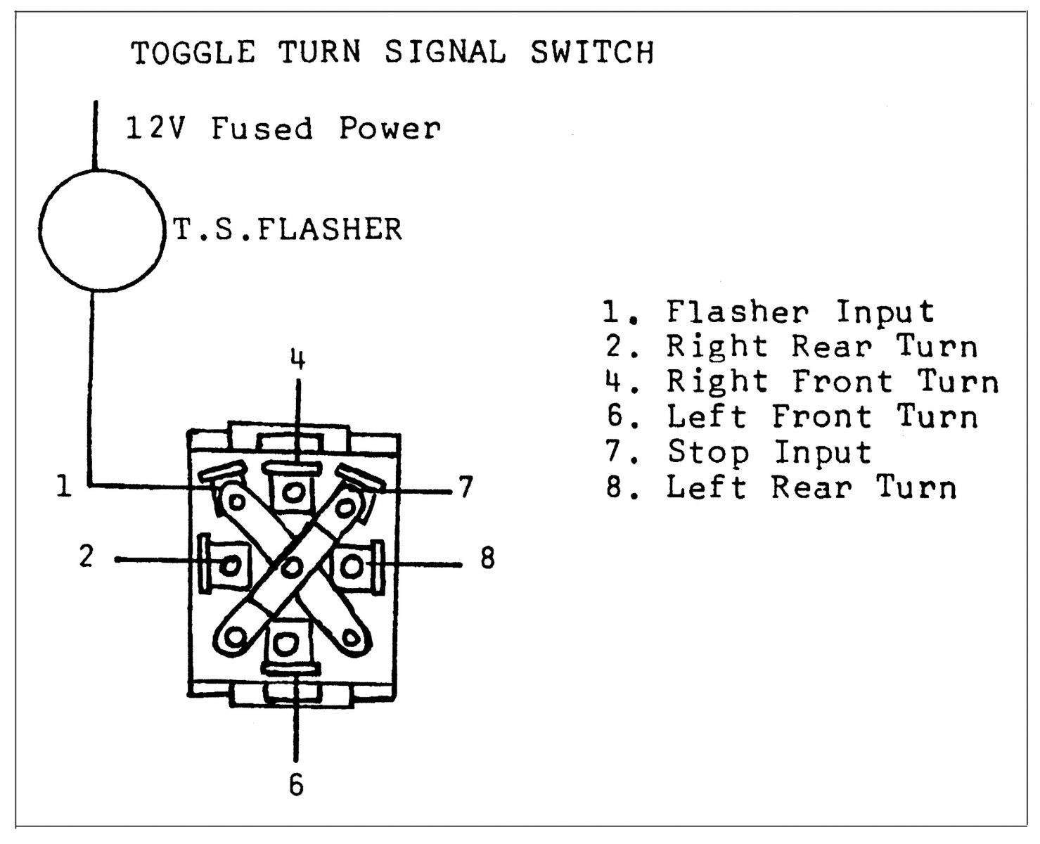
3 Prong Flasher Wiring Diagram Wiring Diagram Image
In conclusion, a parameter diagram for a 3 way valve is an invaluable tool for understanding the inner workings of this crucial component. By considering the valve's position, fluid pressure, and flow rate, engineers can optimize its performance and ensure the smooth operation of their systems.. ← Wiring Diagram 1998 Jeep Cherokee Wiring.
3 Way Stainless Steel Valve at Rs 500 in Mumbai ID 2852383442930

The Honeywell 3 Way Valve Diagram is a highly efficient and reliable plumbing component used in heating, ventilation, and air conditioning (HVAC) systems.. The Ultimate Guide to Understanding John Deere 3010 Wiring Diagram. Related Post. Exploring the Exhaust System Diagram of the 2009 Chevy Malibu 2.4. Understanding the Motorcycle Brake.
[DIAGRAM] Piping Diagram 3 Way Valve

A 3-way valve is a type of valve that has three ports or openings, which allows it to control the flow of a fluid or gas in three different directions. This type of valve is commonly used in industrial and HVAC systems. The operation of a 3-way valve is fairly simple. When the valve is in the "open" position, the fluid or gas can flow.
[DIAGRAM] Pneumatic 3 Way Valve Diagram
Part 4 in the heating wiring series covers how the 3 port mid position valve works internally, allowing 3 separate positions from only 2 mains inputs.Website.
SWITCH WIRING DIAGRAM 3 Zone Valve Wiring Diagram

3-way valve with normally closed actuator (Note: 3-way uses only normally closed actuator) 5 Operation of normally closed valve. Wiring diagram Terminal block To relay, boiler contacts (TT) or DDC system. Thermostat L1 (HOT) L2 24 V only Aux. Switch 0.4 amps max. Caleffi North America, Inc.
electrical Why isn't this 3way wiring working? Home Improvement Stack Exchange
A 3-way air valve is a device used to control the flow of compressed air in various systems and applications. It is an essential component in pneumatic systems, serving as a switch to direct the flow of air in different directions. The valve consists of an inlet port, two outlet ports, and a rotor or slide that controls the air flow.